
Product and process
Thermal Oil Heater and Heat Transfer Systems
A thermal oil heater heats a heat transfer oil in a closed circuit and carries heat to processes at high temperature and low pressure. Unlike steam, it does not need high pressure to reach high temperature. Yeşil Çevre Makine designs, manufactures and installs turnkey the heater, expansion and pump groups, piping and automation, with flow velocities and safety equipment that keep the oil from degrading. Standard heaters range from 660 kW to 5,814 kW.
Comparison
Steam system versus thermal oil system
| Criterion | Steam | Thermal oil |
|---|---|---|
| Pressure at high temperature | Pressure rises steeply with temperature | The oil reaches high temperature at close to atmospheric pressure |
| Water treatment | Feed water conditioning is required | Not required |
| Condensate and blowdown losses | Present | None; the circuit is closed |
| Freezing and corrosion | A risk | The oil does not freeze and does not corrode the circuit |
| Temperature control | Indirect, through pressure | Direct and precise |
| Main risk | Pressure vessel safety | Flammable fluid; leaks and degradation of the oil |
Thermal oil is not the right choice for every process. Where the temperature demand is low, or steam is used in the process itself, steam may be more suitable.
Working principle
How does a thermal oil system work?
The circulation pump drives the heat transfer oil through the heater’s coil tubes. The burner flame heats the coil; the heated oil flows through the closed circuit to the process equipment, that is the drying ovens, rollers, reactors and heat exchangers, gives up its heat and returns to the heater.
The expansion tank takes up the oil’s increase in volume with temperature and keeps the circuit out of contact with air. The venting and fill-and-drain arrangement allows the moisture and light fractions in the oil to be removed safely during commissioning.
The heart of the design
Film temperature and tube velocity: the system decides how long the oil lasts
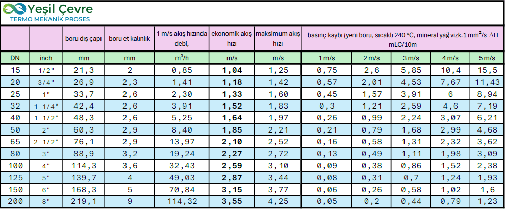
Heat transfer oil usually degrades not because of the oil itself but because of the system design. The thin layer of oil touching the tube wall inside the coil is hotter than the oil’s average temperature. This temperature is called the film temperature, and every oil has an upper limit for it set by its manufacturer.
If the velocity in the tube is too low, the film temperature rises. Once the limit is exceeded the oil cracks thermally: light fractions form and the flash point drops, while heavy fractions carbonise and coat the tube wall. A coated tube conducts heat less well, the wall gets hotter still, and the process accelerates itself. The result is blocked and perforated tubes, falling efficiency and a rising fire risk.
The second path to degradation is oxidation. Hot oil that touches air oxidises, darkens and becomes more acidic. That is why the arrangement of the expansion tank matters: hot oil must not come into contact with air.
- Correct tube velocity: the coil and circuit are sized for velocities at which the oil’s permitted film temperature is not exceeded.
- Flow safety: the burner stops immediately when flow is lost or reduced.
- Correct expansion arrangement: oxidation is prevented with a cold oil cushion or an inert gas blanket.
- Precise temperature control: PLC-based automation keeps the process temperature within a narrow band.
Capacity
Standard thermal oil heater capacities
| Thermal capacity (kcal/h) | Thermal capacity (kW) | Connection size (PN25) |
|---|---|---|
| 567,600 | 660 | DN 65 |
| 817,000 | 950 | DN 80 |
| 1,049,200 | 1,220 | DN 100 |
| 1,290,000 | 1,500 | DN 100 |
| 1,591,000 | 1,850 | DN 100 |
| 1,849,000 | 2,150 | DN 125 |
| 2,150,000 | 2,500 | DN 125 |
| 2,537,000 | 2,950 | DN 150 |
| 3,125,240 | 3,634 | DN 150 |
| 3,405,600 | 3,960 | DN 150 |
| 3,835,600 | 4,460 | DN 200 |
| 4,150,000 | 4,826 | DN 200 |
| 5,000,000 | 5,814 | DN 200 |
Custom designs are made for requirements outside this range. Fuel type and burner selection are decided according to the plant’s conditions[C-02].
Standards
The standards and directives our design and manufacturing follow
| Standard / directive | Scope |
|---|---|
| DIN 4754[R-09] | Heating plants using organic heat transfer fluids: safety requirements and testing |
| VDI 3033 | Guideline for the design and operation of heat transfer plants |
| EN 13445 / EN 13480 | Unfired pressure vessels and metallic industrial piping |
| 2014/68/EU[R-11] | Pressure Equipment Directive |
| 2006/42/EC[R-10] | Machinery Directive. To be replaced by Machinery Regulation (EU) 2023/1230 from 20 January 2027 |
| DIN EN ISO 3834-2 | Quality requirements for welded manufacturing |
| ISO 9001:2015, AD 2000 | Quality management and pressure vessel design rules |
The list of standards is a company statement[C-04].
Integration
Designed together with solvent recovery plants
The drying ovens on printing, laminating and coating lines are largely heated with thermal oil. As a company that builds both the solvent recovery plant and the heat centre for the same plant, we treat the two systems together.
The recovery line has steps that need heat, such as distillation and regeneration. That heat can be taken from the existing thermal oil circuit. Waste heat in the heater’s flue gas is recovered with a waste heat boiler and heat exchangers, lowering total fuel consumption. When the exhaust flow of the dryers is reduced with L.E.L. control, the heater load falls too.
Product and service scope
The whole heat centre from one source
Equipment: thermal oil heaters, burners and stacks, thermal oil heating units, waste heat boilers, heat exchangers, combustion air pre-heaters.
Circuits: heating, cooling and chilling systems, temperature control units, secondary circuits.
Project: preliminary site survey, design, manufacturing, installation and turnkey plant construction.
Commissioning: installation supervision, commissioning, training of operating and maintenance staff.
Operating support: maintenance and repair, spare parts, plant modernisation.
Regulatory process: support with the statutory procedures.
Commissioning
The oil’s life is decided on the first day
Pressure and leak test
The circuit is tested before it is filled with oil; welds and flange connections are checked.
Filling and venting
The oil is filled slowly from the bottom. Air in the circuit is vented from the high points.
Staged heating
The temperature is raised in stages. Moisture in the oil and the circuit evaporates and is removed through the expansion tank; skipping this step causes pump cavitation and sudden pressure surges.
Verification of the safeties
The flow, temperature, pressure and level safeties are triggered one by one to verify the burner lockout.
Training and oil monitoring plan
Operators are trained. A sampling point and monitoring interval are set for periodic analysis of the oil.
From the field
What sits where in a thermal oil heater room?
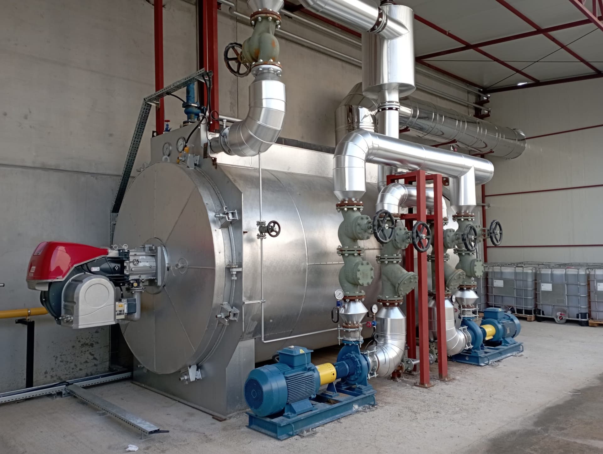
The photograph is a site view of a system we built. The numbers mark only equipment visible in the photograph.
Burner
Mounted on the heater’s front door; its flame heats the coil through which the heat transfer oil flows.
Insulated heater body
The coil tubes are inside this body. The oil is heated through the tube wall, not directly by the flame.
Circulation pump
Circulates the oil in a closed circuit between the heater and the process equipment. Two pumps are visible in the photograph.
Valve and strainer group
Isolation valves, strainers and pressure gauges on the pump suction and discharge lines.
Insulated flow and return lines
Carry the heated oil to the process and bring the cooled oil back to the heater.
Gallery
Thermal oil systems we have installed
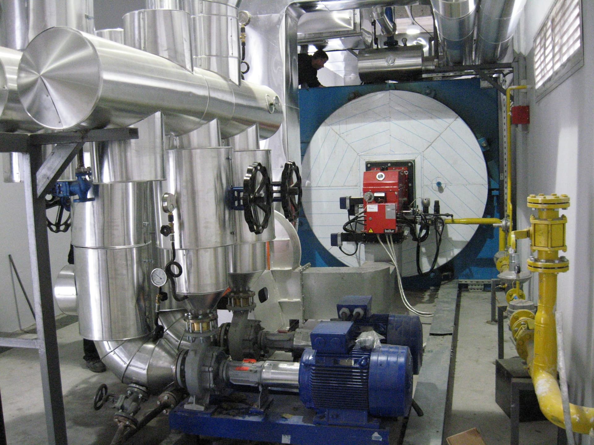
Thermal oil heater, burner and circulation pump 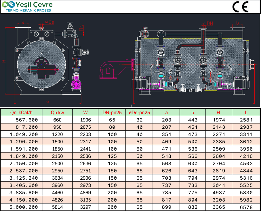
Thermal oil heater technical drawing and capacity table
Frequently asked questions
Frequently asked questions about thermal oil heaters
What is a thermal oil heater?
A thermal oil heater is an industrial heating system that heats a heat transfer oil in a closed circuit and carries the heat to processes. Because it reaches high temperatures at low pressure, it is simpler to operate than high-pressure steam systems.
What is the difference between a thermal oil system and a steam system?
In steam systems pressure rises steeply with temperature. In thermal oil systems the oil reaches high temperature at low pressure. There is no water treatment and no condensate or blowdown loss, and temperature control is more precise.
Why does heat transfer oil degrade?
Heat transfer oil degrades mostly because of the system design. A low tube velocity raises the film temperature and the oil carbonises; contact between hot oil and air causes oxidation. The right velocity, the right expansion arrangement and safety equipment extend the oil’s life.
In which capacities are the thermal oil heaters built?
Yeşil Çevre Makine builds its standard thermal oil heaters in 13 capacities from 660 kW to 5,814 kW, that is 567,600 to 5,000,000 kcal/h. Other capacities are designed for the specific plant.
To which standards are the thermal oil heaters built?
Yeşil Çevre Makine states that its thermal oil systems follow the requirements of DIN 4754, VDI 3033, EN 13445, EN 13480, DIN EN ISO 3834-2, the Pressure Equipment Directive 2014/68/EU and the Machinery Directive 2006/42/EC. The scope of certification is settled for each project at the proposal stage.
Sources and method
What the information on this page rests on
This page was prepared by Yeşil Çevre Makine using the company’s product catalogue, photographs from its site installations and the public sources listed below. Information that is a company statement is marked as such in the text. Project-specific values (capacity, emission, recovered quantity) are determined for each plant at the survey and design stage.
Official regulation and standards
Primary sources; links go to the official publication pages.
- R-09DIN 4754-1:2015-03 Wärmeübertragungsanlagen mit organischen Wärmeträgern. Teil 1: Sicherheitstechnische Anforderungen, PrüfungDIN (Alman Standartlar Enstitüsü) · Mart 2015 · Accessed: 18 Eylül 2026 · Standart metni ücretlidir; yalnızca kapsamına atıf yapılmıştır
- R-10Regulation (EU) 2023/1230 on machineryAvrupa Birliği; özet: EU-OSHA · 14 Haziran 2023; uygulama 20 Ocak 2027 · Accessed: 18 Eylül 2026 · 2006/42/EC sayılı Makine Direktifi'nin yerini alır
- R-11Directive 2014/68/EU (Basınçlı Ekipmanlar) ve Directive 2014/34/EU (ATEX)Avrupa Birliği, EUR-Lex · 2014 · Accessed: 18 Eylül 2026
Company statements and documents
Statements resting on these sources are Yeşil Çevre Makine’s own; they have not been verified by an independent body.
- C-02Kızgın yağ kazanı teknik çizimi ve kapasite tablosuYeşil Çevre Makine · 2025 · Accessed: 18 Eylül 2026 · Şirket belgesi; sayfadaki teknik çizim görselinden aktarılmıştır
- C-04Yeşil Çevre Makine kurumsal bilgileri ve hizmet kapsamıYeşil Çevre Makine · 2022–2025 · Accessed: 18 Eylül 2026 · Şirket beyanı
Request a site survey and pre-feasibility for your line
Tell us the solvent, the approximate consumption and the line. Our engineers call you to clarify the need and, where useful, plan on-site measurements.
What we ask for
- Solvent type
- Consumption or air flow
- Sector and line type
- Project stage
To reach us directly: +90 506 839 88 57 · info@yesilcevmak.com